Typical Sound Card & Computer Connections
|
There are many commercially manufactured sound card interfaces on the market (more...). Below are some basic circuits that may be utilized. More information here... An inexpensive and good isolation transformer is available at BuxComm.com model number XFMR115. This transformer has a good low end frequency response down to 75 Hz at -6 dBv. W2IHY has a ready built audio interface unit that may be used to interface your sound card to your radio. Please note the I-Box from W2IHY does not have any serial port support, but will work if you desire to just use the equalizer for transmitting only. Another inexpensive solution to the isolation transformer is a "Direct Box" used by the music industry. Most use the standard 1/4 inch phone jack for the input(s) and an XLR connector for the output. To wire the XLR output connector to a transceivers microphone, use the XLR plus (pin 2) to the transceivers microphone in, and the XLR minus and ground (Pins 1 and 3) to the transceivers microphone minus. Click here for one from Musicians Friend.
|
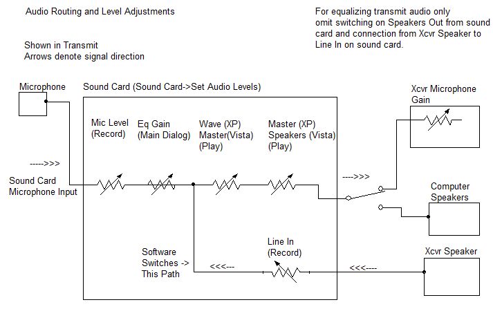
Overview of audio routing and audio level controls.
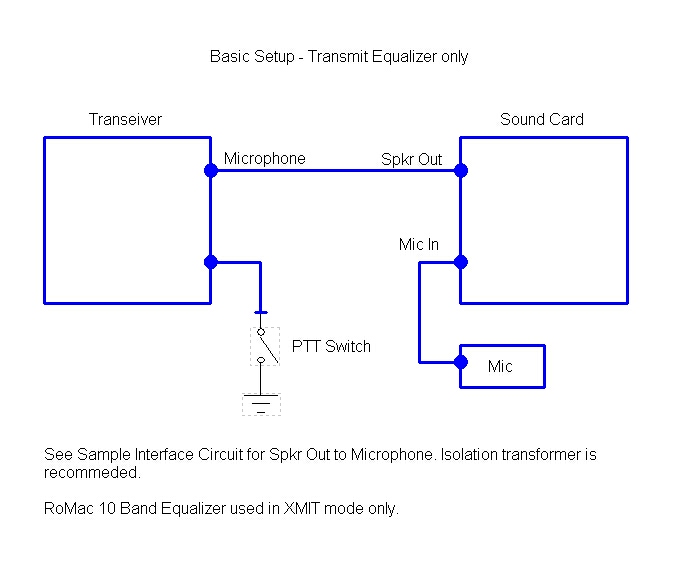
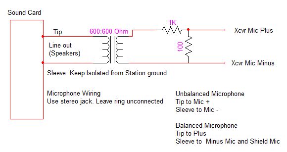
Basic radio and interface connections for
equalizing just the transmit audio.
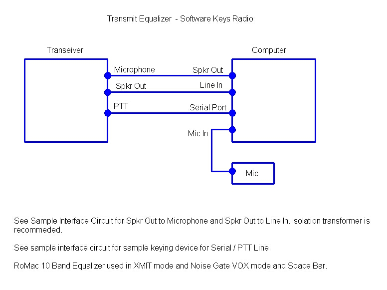
Software in "Xmit Only" mode and Serial Port Support turned off, or using
a separate serial cable for CAT commands, for
proper signaling for the CW I'der
See Help File for Serial Port setup.
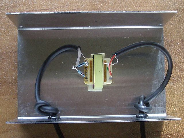
Picture of Basic Interface - Built in small aluminum project box. The input on
the right uses a stereo cable wired just for the left channel (tip on jack). The
output on the left is a monaural audio cable. The
isolation transformer is secured with double sided tape. The audio cables
and project box are available from Radio Shack . A monaural cable is available
with a jack on one end, and tined leads on the other. The stereo cable came with
a jack on both ends. I just cut one of them off. Keep the cables as short as
practicable, yet leave enough to install the ferrite common mode choke.
Note: Bringing the cable in through a hole (with a grommet) addresses
the issue of not grounding the "sleeve" coming from the sound card.
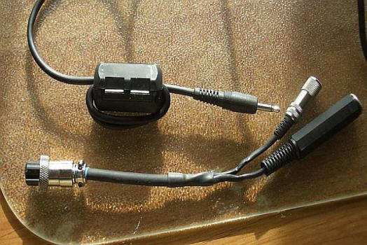
The microphone is connected directly to the sound cards microphone input, with a ferrite choke on the sound card end.
Picture of adapter to transceiver and ferrite choke (three turns) (Mouser part number 623-0431167281) on audio line. Two ferrite chokes, one at the sound card and and one at the transceiver end. 8 pin microphone Adapter shown is a Heil adapter for their headsets. The large female jack is for a foot switch. W2ENY offers similar adapters. A similar adapter is easily homebrewed. You could omit the small jack for the audio line and hardwire the audio cable to the 8 pin connector. Consult your transceivers manual for the pin out of the microphone connector.
Complete Interface circuit that supports all modes of the
RoMac 10 Band EQ and Receive Filtering software. Bypass capacitors omitted for
clarity.
Use .01 uF on all 12 VDC lines and PTT line
Further information can be found in the Help File
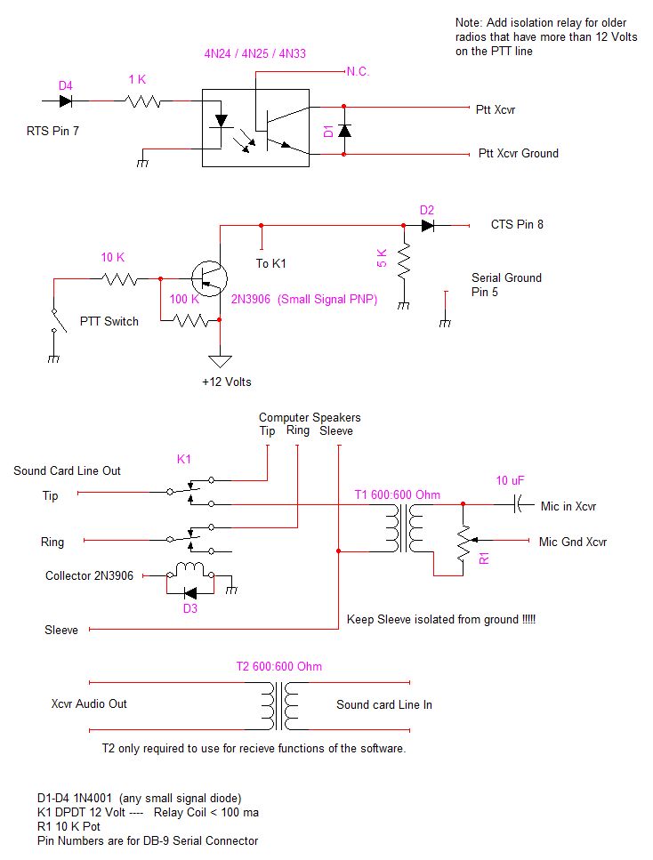
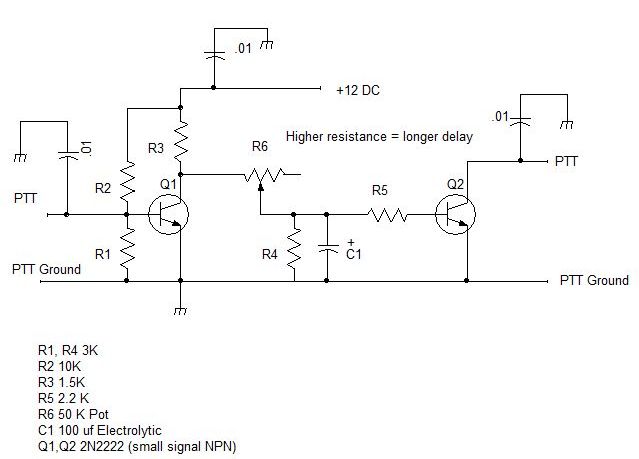
PTT delay circuit for sound card that exhibit a "noise burst" going from
receive to transmit in the "Rig Interface Mode".
Starting with Version 2.9.0 the software now has
option of responding to a CTS signal before placing the sound card interface
into transmit. This allows the software to program the proper delay before
placing the sound card interface into a transmit mode.
See software's help file for more information
under "Noise Burst - Rig Interface Mode". There you will find further
explanations and modifications for RigBlaster Pro and RigBlaster Plus to utilize
the new delay feature in the software.
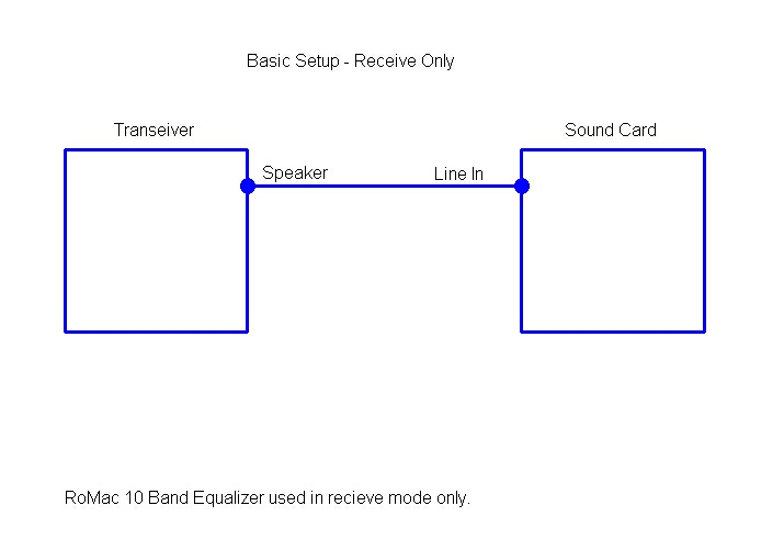
Simplified block diagrams of hookups